The User flows module
The User flows module offers a robust diagraming tool that can be connected to the rest of your prototype. It can provide the stakeholders of your projects different ways to visualize that are hard to visualize in the prototype. The typical usages of User flows are to diagram user Flows, simulate and validate them.
Overview
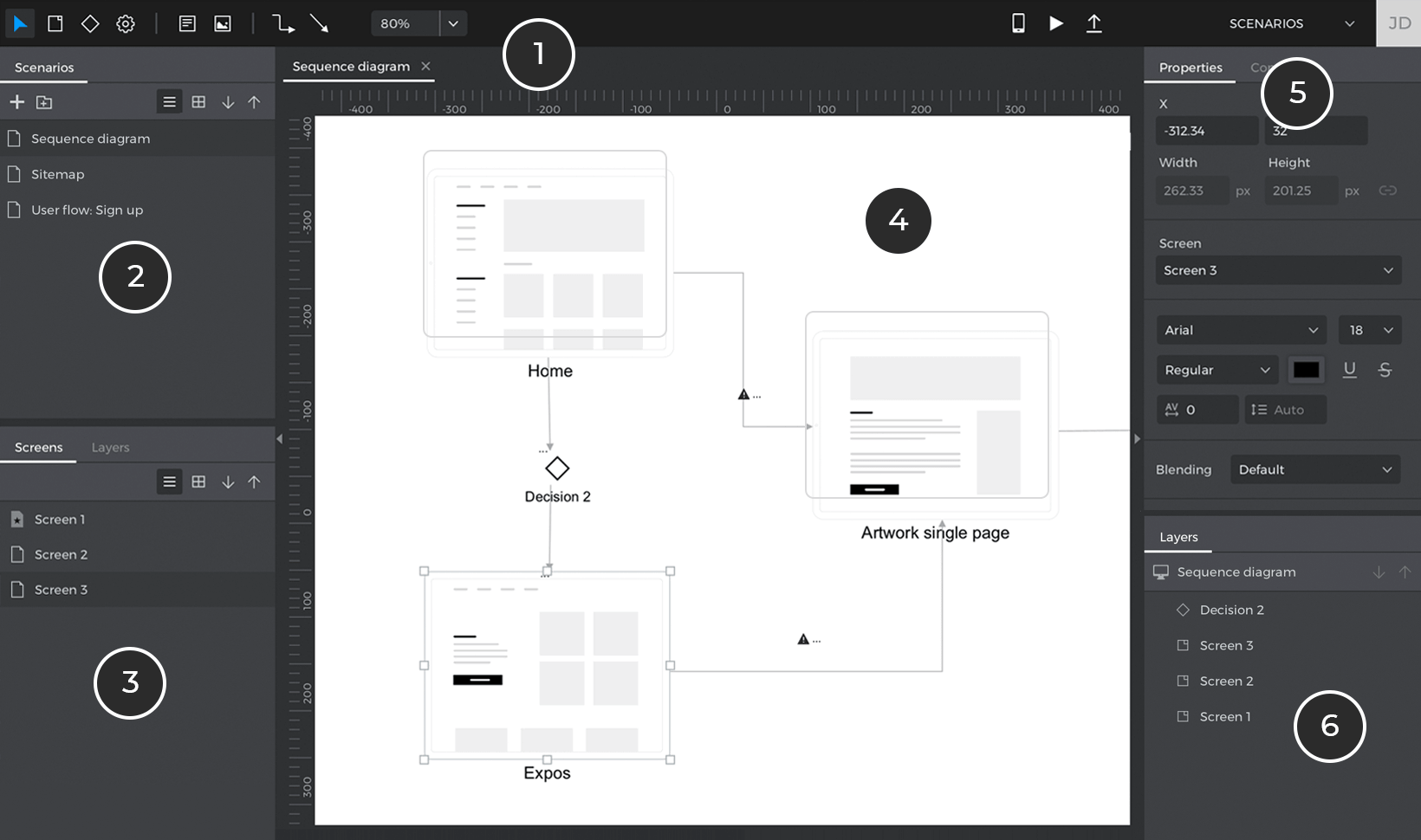
- Toolbar – here you can find all the elements to draw a user flow in the canvas. You’ll find components like Screens, Actions, Decisions, Notes (text boxes), Images or connections to connect all those elements together. You can also launch the simulation of your user flow. You can find a detailed description of each element of the toolbar in the next section.
- Boards – a list of all the boards you’ve created. You can change the board displayed in the canvas by clicking the boards in this list.
- Screens – the screens of the prototype you’re currently working on the UI module. If you drag a screen to the prototype, a Screen element will be added to the board linked to that screen.
- Canvas – displays the contents of the Board. You can use the tools in the toolbar or the screens in the palette to lay out your user flow.
- Properties – a list of properties for the selected element in the canvas. You can edit many style properties of each element to make them your own.
The User flows module toolbar
In the User flows toolbar you can find the following options:

- Home – go to your Home screen.
- Select tool – click here to change from a different tool to the selection tool.
- Screen tool – click and then click again in the canvas to add a Screen element to the board. Screen elements are just icons in the diagram by default but you can link them to specific screens in the prototype using the Properties palette. Once linked, the icon will be replaced by a synchronized screenshot of the linked Screen.
- Decision tool – click and then click again in the canvas to add a Decision element to the board. Decisions are just for diagramming purposes, they don’t affect the navigation of your prototype.
- Action tool – click and then click again in the canvas to add an Action element to the board. Actions are just for diagramming purposes, they don’t affect the navigation of your prototype.
- Connector tool – click and then click again in the canvas to add a Screen element to the board. A connector is a diagramming element that is used to start / end a user flow.
- Text tool – this tool allows you to write text in your diagrams.
- Note tool – you can use this tool to draw text boxes in your diagram. Notes are highly customizable and can be use to draw any kind of diagram.
- Image tool – clicking this tool will allow you to add any image file to the board.
- Connection tools – this tool is used to add connections between elements in the diagram. The first type of connection will be rectilinear, and the second one straight. You can change that in the Properties palette.
- Zoom level – you can control the level of zoom in the canvas using this component. Clicking on the arrow will show additional zooming options.
- View on device, Simulate and Share – equivalent to the same icons in the User Interface module.
Creating a new board
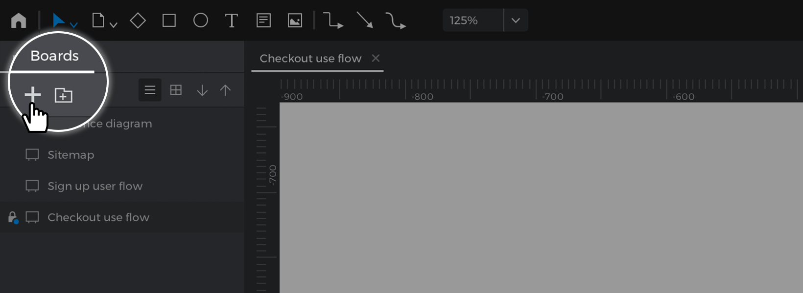
To create a new board, click the ‘+’ icon in the Boards palette. Here, you will also see a list of all the boards you’ve created. If you want to open a board, just click on it. Double-clicking will allow you to rename a Board and right click (ctrl+click on Mac) will show additional options.
Diagramming transitions and flow validation
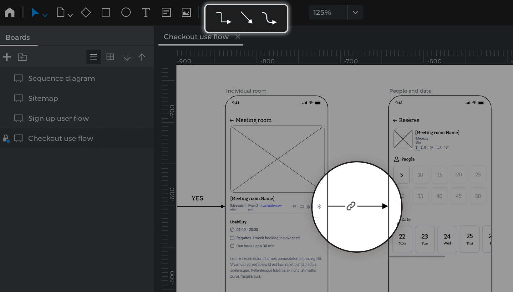
You can draw connections between elements in your diagram by using the Connection tools from the toolbar. First, click on one of those tools and you’ll see the cursor change. Move over one of the elements you may have on your canvas and you’ll see a preview of the starting point for that connection. Click and drag to another element in the canvas to create a new connection.
You can customize the look and feel of that connection in the Properties palette. If the connection is between two screens, Justinmind will check if that implied navigation matches any of the events created in those screens in the User Interface module. If not, then a warning icon will show up. If at any point you create a navigation event between those screens, the warning message in those connections will go away.
All information in the diagram can be exported to a MS Word document along with the rest of the information of the prototype. Use the main menu options ‘File – Export – Spec. document/Customize spec. document’.
Creating screens from User flows module
User flows can be a good starting point to design your applications, before getting into the details of the contents of each screen and their interactions. In many methodologies, defining User Flows is the first step before getting into UI / UX design or even wireframing. The good thing is you don’t have to do the work twice since you can create Screens from the screen palette or the toolbar. To do so, right-click on a screen and select the option ‘Edit screen’. A new Screen will be added to the prototype with the name you set up in the User flows module and you will automatically be taken to that screen in the User Interface module.
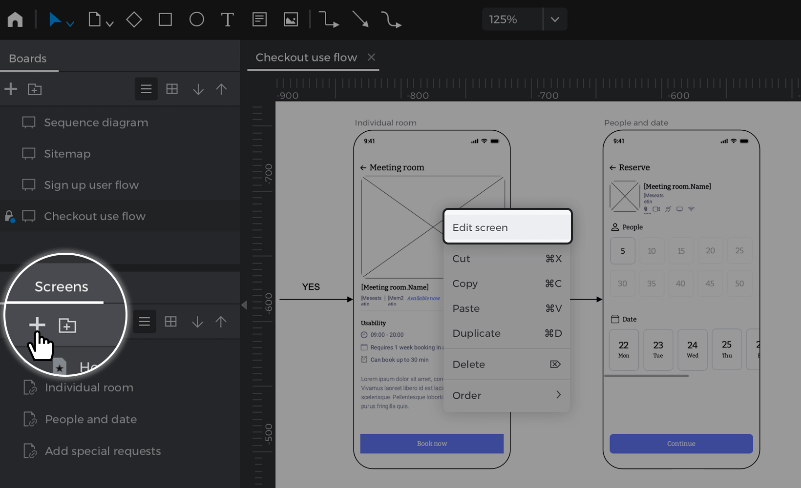
Then, you can design the content and interactions of that screen to flesh out the navigation flow. If you go back to your Board, you will see a synchronized screenshot of the actual screen.
Simulating user flows
You can display your user flow in your simulation as if they were any other screen. Once in the Simulation mode, you can even restrict the navigation of your prototype by what is defined in one of your user flow. For that, follow these steps:
- Go to the toolbar and click the ‘Play’ icon to launch the simulation.
- In the Simulation mode window that appears, click on the hamburger menu in the top right-hand corner. A slide menu will appear with two tabs: “Screens” and “User flows”.
- Go to the “User flows” tab and select the board where the user flow you wish to simulate is located.
- In the simulation Canvas, click on the component where you defined the beginning of your navigation flow. In the pop up that appears, click “Start”. Then the simulation will launch that screen but only the navigation events that match the arrows in that flow will work. You can preview the step you’re in your flow on the top bar.
You can stop the current simulation and/or change the navigation flow, remove the filter in the top toolbar of the Simulation window like so:
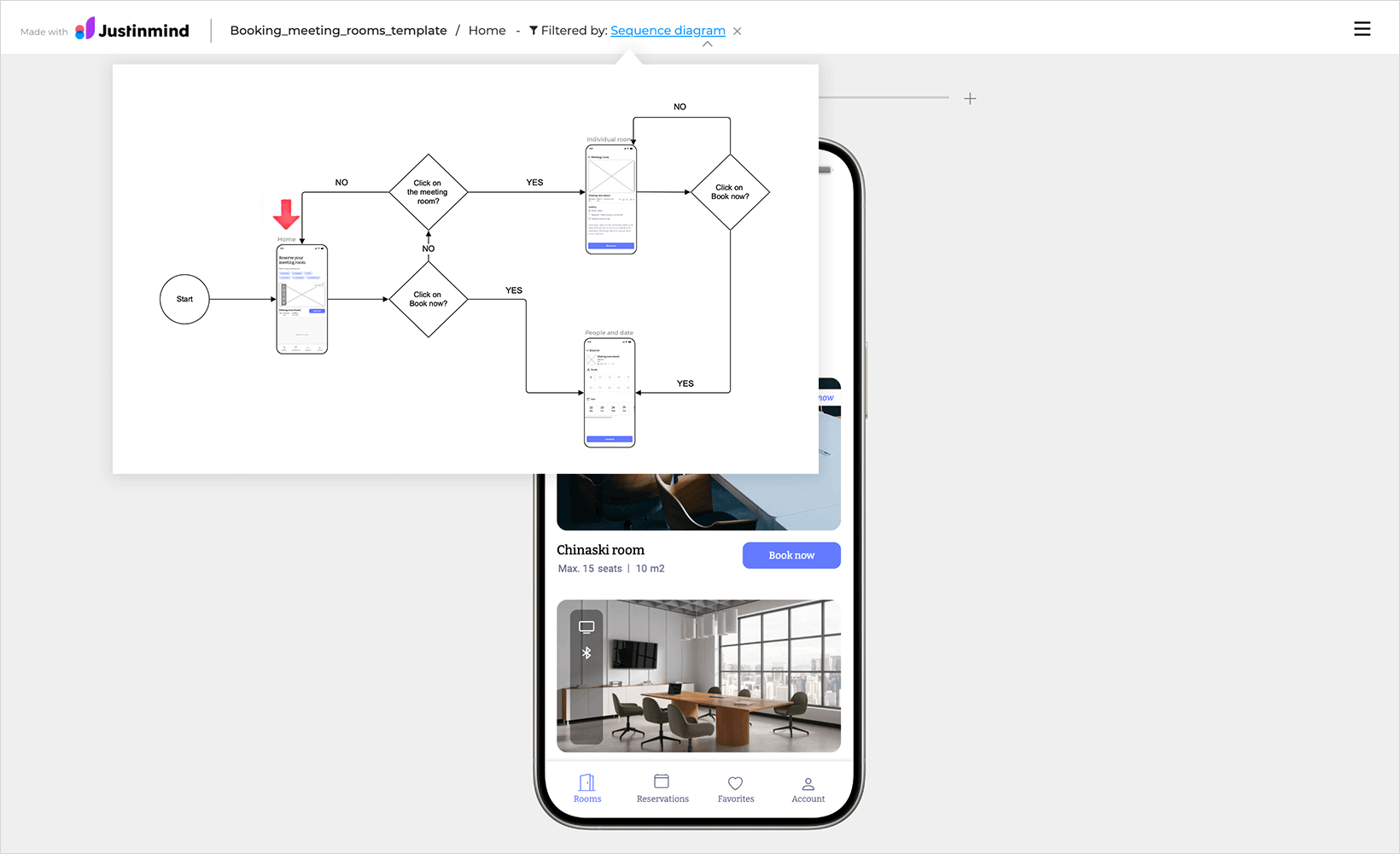
Reviewing
If you share your prototype you have the option to also share the flow in that prototype. Reviewers will then be able to see the diagrams and add comments to them. They can even add comments to specific elements within a flow.
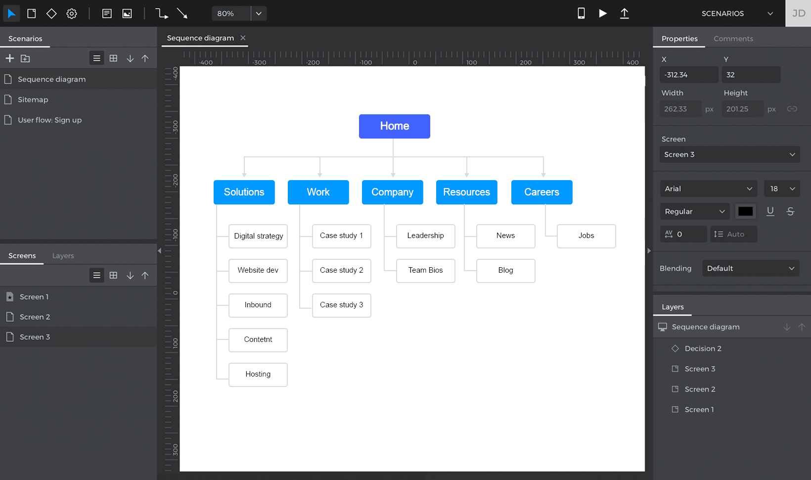
Diagramming site maps
It’s really easy to diagram a site map using the User flows module. First click on the Note tool and then on the Canvas. Customize the look and feel of that note for your liking using the Properties palette. Then copy and paste that Note (or text box) for as many screens you’re defining in your Site Map. Finally, use the connection tool to diagram your Site Map and define the hierarchy of your screens.
